3. Container description
3.1. Power supply & plug
All refrigerated containers utilised in the Australian trade operate on 440 volt/ 60hz and onboard vessels they operate on 415 volt/ 50hz within Australian ports.
The power cable is fitted with an ISO standard CEE-17 plug. Care must be taken to ensure that plug is not damaged (cable length - 18 metres).
If the safety plug is damaged or tampered with there is a possibility of electrocution or fire if used incorrectly; if a damaged plug is encountered, do not plug into power & advise the Shipping Company of the situation immediately.
3.1.1. A container used for the refrigerated shipping of produce is essentially an insulated box to which a supply of refrigerated air is attached. Most containers used from Malaysia have external dimensions of;
6.06 (L) x 2.438 (W) x 2.438 or 2.591 (H) m.
12.192 (L) x 2.438 (W) x 2.591 or 2.895 (H) m.

3.1.2. An integral container has a refrigeration unit built into the end of the container. The unit has its own temperature control system and fans to circulate the refrigerated air. The refrigeration unit is fitted with some form of visible temperature indicating devices and all containers have Temperature Recording device (s). Although there are still many containers in existence with “Partlow” or similar circular 31 day chart recording equipment these are now being phased out and replaced by electronic data recorders which generally need to be electronically downloaded to provide voyage carriage temperature and unit operational, alarm and performance history. Some containers are fitted with both a chart and electronic recorders but this is because some owners elect to have both, to allow for industry transition from chart recorders to more modern technology. Those packers, shippers’ freight depots and carriers who have chart operations included in their procedures or practices should be aware of this technology change and progression.
3.1.3. In integral containers, depending on the design of the unit, the refrigerated air is supplied either at floor level or at ceiling level; the containers are said to have either bottom air delivery or top air delivery, respectively. The greater percentage of integral containers currently in service has bottom air delivery.

3.1.4. The unit attached to a container is designed only to maintain produce temperature and cannot reduce produce temperature quickly. Thus, ideally packers should ensure that produce is within 1°C of the desired carriage temperature before loading into the container and the unit should be placed and kept on power as soon as possible after stowing of the produce is complete (Refer to Table 1 & 2 in Appendix 1).
NOTE: The refrigeration units should never be run with the container doors open, except where the container is sealed into an anti-chamber loading dock. If left open, condensation and moisture will be drawn into the container and across the evaporator coils. This will cause the evaporator coil to ice up and possibly cause the reefer container to malfunction and damage to the cargo. Condensation may also form on the cargo and packaging, resulting in ‘cargo sweat’, which could weaken any fibreboard packaging.
3.1.5. Except in cold climates, the temperature of the circulating refrigerated air rises as the heat leaking into the container or generated by the produce is absorbed by the air. Thus, the temperature of the return air is warmer than the delivery air; the difference is normally 1 to 2°C for chilled cargo (lower for hard frozen cargo), but can be as high as 3°C and higher during initial temperature pull down of loads. (This excludes the temperature rise of the air due to heat from the circulating fans, as this temperature rise is external to the cargo space).
3.1.6. Containers (6 m long) have nominal heat leakage rates of 20 to 30 W/C (Watts per degree Celsius temperature difference across the container walls). At ambient temperatures above about 20°C the major heat load on the refrigeration unit is heat leakage through the container walls and consequently the major portion of the circulating air should flow over the internal surfaces of the container rather than through the stow.
3.1.7. Produce is not at a uniform temperature throughout a refrigerated container. The coldest produce is near the point where the refrigerated air enters the container. The position of the warmest produce depends on the type of container, but is commonly near the doors (at the top of the reefer around 700 mm from the door). The spread in temperature depends on the ambient temperature, the total air circulation rate and its distribution, the temperature uniformity of the air delivered to the container, and the respiration heat of the produce; the distribution is determined by the basic design of the circulating system and by the stowage of the produce.
3.1.8. The temperature controller on the integral or clip-on unit may be controlled from a sensor placed either in the air entering or the air leaving the container cargo space; the unit is said to operate under delivery air or return air control respectively. 3.1.9 With modern integral containers fitted with electronic/programmable controllers, it is normal for equipment to control delivery air for chilled cargoes, eg. horticultural produce, (and control return air for frozen commodities, eg. hard frozen meat).
3.1.10. Electronically controlled refrigeration units have 3, 6, 12 or 24 hourly defrost cycles (that can be set on the control setting), which last for approximately 30 to 40 minutes. An example of a regular 6-hour defrost recording on a Partlow chart can be observed in Figure 2. The periodic defrost cycles prevent ice build up on the surface of the evaporator coils, which can restrict the airflow through the coils and therefore reduce the refrigeration capacity of the container (see Figure 2).
NOTE: A normal defrost cycle does not heat the cargo, only the evaporator coil and the immediate air chamber is heated. During this time there is no airflow to interior of the container and therefore no measurable effect to the cargo.


3.2. Pre Trip Inspection (PTI)
All refrigerated containers are inspected prior to being released to the shipper/packer or his trucker. The refrigeration units integral to containers or in clip-on units, as well as the associated temperature controllers, are checked for proper operation before being despatched for cargo packing - this is referred to as a 'pre-trip'. This procedure is an extensive technical check of the reefer machinery and the container. Technicians use pre-determined comprehensive checklists to ensure that the container is clean, undamaged and that the reefer machinery is in ideal running condition. Technicians conduct PTI in accordance with shipping company requirements and procedures. The Pre-Trip Inspection (PTI) of refrigeration equipment also includes a check of the temperature control/recording instrumentation using an electronic digital thermometer that has been calibrated at 0°C in an ice/water slurry. It is important to ensure the drains, collection pan and evaporator coil are cleaned and free of debris during the pre-trip inspection (PTI) of the reefer machinery. At least one defrost cycle should be completed in accordance with the machinery manufacturers instructions at the time of PTI. On completion of the pre-trip service a decal is attached to the machinery end of the container clearly indicating the date of checking. The validity of a pre-trip service is commonly regarded as current for one month from the date entered on the pre-trip decal (different shipping companies may have differing validity periods).
As the intended use of the container is not usually known when the PTI is carried out, the Set Point may be left on a temperature to suit the carriage of Hard Frozen or Chilled cargo (eg. -18° C or 0°C). The Set Point Temperature must be checked before the container unit is placed on power.
On mechanical temperature controllers (Partlow Controller or separate dial setter) the setting can be verified before placing the machinery on power. Electronic temperature controllers may require the machinery to be placed on power, unless the temperature controller is fitted with its own power source. The majority of containers have simple clear starting instructions.
3.3. Set Point
The Set Point is the temperature setting on the controller of the refrigeration unit. For units with delivery air control, the supply temperature will be 0.5 to 1.5°C below the desired carriage temperature. For units with return air control, the set-point temperature will be approximately +2°C the desired carriage temperature, providing the cargo has been pre-cooled to the desired carrying
temperature. For produce with a recommended storage temperature at or below 0°C, the set point may need to be set at a higher value than the storage temperature to avoid possible chilling injury or freezing of the produce; the need to do this depends on the type of container and control unit that is used. It is essential that container operators know what kind of equipment is under their control, as it is their responsibility to provide a container suitable for the produce to be packed.
(See also paragraph 8.1.3; shippers responsibility to give all relevant details of product to be carried in order that the shipping company can make available a container suited for the carriage of that product)
3.4. Fresh Air Exchange
Ethylene and CO2 levels in containers are regulated by ventilating with vents (air freshening) - it is essential that the outside air is free of ethylene (Note: Vents should be closed during road travel to prevent ethylene contamination from vehicle exhausts). Ventilation is achieved by opening vents that are fitted across the fan; the fan pressure causes fresh air to flow in one vent and air containing the evolved gases to flow out the other vent. All containers used for fresh produce must be fitted with a means of ventilation. Loading cargo above the maximum ‘red line’ height can affect fresh air exchange). Note that CA containers operate with these vents closed at all times. Some MA
containers (such as AFAMI) operate with electronically controlled vents to regulate gas conditions around the cargo. Loading cargo above the maximum ‘red line’ height can affect fresh air exchange). Ventilation should be undertaken to keep the CO2 level below the maximum specified in Tables 1 & 2, in Appendix 1. Excess ventilation is of no value to the produce and can cause excessive amounts of water to condense on the evaporator coils. If this water turns into ice it may restrict the airflow, thereby increasing the temperature spread in the stow. (See Section 3.1.10).
3.5. Controlled Atmosphere (CA) and Modified Atmosphere (MA or AFAM+)
Controlled or modified atmospheres normally are not provided in general refrigerated containers. In suitable containers, it is possible to provide CA or MA conditions (at additional cost) on a one-trip basis. For almost all CA/MA systems now in use the containers must meet a stringent gas-tightness specification and are usually fitted with a plastic sheet inside the doors to avoid the possible problems of leaking door seals. There are some containers especially designed for CA transport. CA containers allow the controlling of the container environment more precisely. Harvested fruit and vegetables continue to breathe until they are consumed or destroyed by decay or desiccation. Under normal circumstances these factors determine the lifespan of the product. The ripening process may be decelerated and the lifespan of a commodity may be prolonged by keeping the produce at optimal temperature coupled with the most effective blend of oxygen, carbon dioxide and nitrogen. Unlike CA and MA units, Automated Fresh Air Management (AFAM)+ uses fresh air exchanges controlled by sensors, which regularly read the O2 and CO2 levels inside the container. If the atmosphere is not at the pre-set AFAM+ level, the vent is adjusted mechanically to achieve the required levels.
3.6. Relative humidity
The quality of horticultural produce is directly affected by the relative humidity of the surrounding air. If the humidity is too low, the produce may wilt and shrivel, whilst if it is too high the produce may develop mould. There have been technical advances made in recent years to build refrigerated containers with advanced humidity control systems. Most require a relative humidity of around 90% to be maintained and this is maintained by the transpiration of the produce, when the ventilation and temperature controls of the container are set at an optimal level. Modern containers with advanced humidity control systems are equipped with a water source, a pump and a water atomiser that
introduces moisture into the container’s air stream. Some reefer containers are fitted with de-humidification equipment, which can reduce the relative humidity of the container to a level of between 50 and 80%.
3.7. Container damage
Every precaution must be taken to ensure that the container and its machinery is not damaged during transport or packing. While the use of freight containers substantially reduces the physical hazards to which cargo is exposed to, improper or careless packing of cargoes may result in serious and costly damage to the container.
The front end of the container houses the machinery, its evaporator and the air circulation system. This machinery is protected by grilles and reasonably robust panels, which can withstand normal wear and tear associated with acceptable methods of loading. However, the impact from careless stowing
(improper handling - such as throwing of cargo) could damage and distort the panels and machinery. Damage to the insulating envelope will result in loss of thermal efficiency leading to a reduction in insulating properties.
NOTE: Great care must be taken if forklifts are utilised to stow a refrigerated container. Adequate protection must be provided, in way of plywood or steel sheet flooring of appropriate strength, prior to utilising forklifts or other heavy equipment within the reefer container, to ensure that the ribs on the floor are not damaged.
3.1. Power supply & plug
All refrigerated containers utilised in the Australian trade operate on 440 volt/ 60hz and onboard vessels they operate on 415 volt/ 50hz within Australian ports.
The power cable is fitted with an ISO standard CEE-17 plug. Care must be taken to ensure that plug is not damaged (cable length - 18 metres).
If the safety plug is damaged or tampered with there is a possibility of electrocution or fire if used incorrectly; if a damaged plug is encountered, do not plug into power & advise the Shipping Company of the situation immediately.
3.1.1. A container used for the refrigerated shipping of produce is essentially an insulated box to which a supply of refrigerated air is attached. Most containers used from Malaysia have external dimensions of;
6.06 (L) x 2.438 (W) x 2.438 or 2.591 (H) m.
12.192 (L) x 2.438 (W) x 2.591 or 2.895 (H) m.
3.1.3. In integral containers, depending on the design of the unit, the refrigerated air is supplied either at floor level or at ceiling level; the containers are said to have either bottom air delivery or top air delivery, respectively. The greater percentage of integral containers currently in service has bottom air delivery.
Examples of different machinery types with common function but differently arranged venting mechanisms, operating devices, reefer machinery and evaporator access
arrangements.
Typical internal view showing Airflow floor and front bulkhead with bottom air delivery and top air return panels. Also shows position of maximum cargo height line when container is used for refrigerated or temp controlled cargo
(usually 100 mm from top in 6M container and 150/200mm for 12M container).
3.1.4. The unit attached to a container is designed only to maintain produce temperature and cannot reduce produce temperature quickly. Thus, ideally packers should ensure that produce is within 1°C of the desired carriage temperature before loading into the container and the unit should be placed and kept on power as soon as possible after stowing of the produce is complete (Refer to Table 1 & 2 in Appendix 1).
NOTE: The refrigeration units should never be run with the container doors open, except where the container is sealed into an anti-chamber loading dock. If left open, condensation and moisture will be drawn into the container and across the evaporator coils. This will cause the evaporator coil to ice up and possibly cause the reefer container to malfunction and damage to the cargo. Condensation may also form on the cargo and packaging, resulting in ‘cargo sweat’, which could weaken any fibreboard packaging.
3.1.5. Except in cold climates, the temperature of the circulating refrigerated air rises as the heat leaking into the container or generated by the produce is absorbed by the air. Thus, the temperature of the return air is warmer than the delivery air; the difference is normally 1 to 2°C for chilled cargo (lower for hard frozen cargo), but can be as high as 3°C and higher during initial temperature pull down of loads. (This excludes the temperature rise of the air due to heat from the circulating fans, as this temperature rise is external to the cargo space).
3.1.6. Containers (6 m long) have nominal heat leakage rates of 20 to 30 W/C (Watts per degree Celsius temperature difference across the container walls). At ambient temperatures above about 20°C the major heat load on the refrigeration unit is heat leakage through the container walls and consequently the major portion of the circulating air should flow over the internal surfaces of the container rather than through the stow.
3.1.7. Produce is not at a uniform temperature throughout a refrigerated container. The coldest produce is near the point where the refrigerated air enters the container. The position of the warmest produce depends on the type of container, but is commonly near the doors (at the top of the reefer around 700 mm from the door). The spread in temperature depends on the ambient temperature, the total air circulation rate and its distribution, the temperature uniformity of the air delivered to the container, and the respiration heat of the produce; the distribution is determined by the basic design of the circulating system and by the stowage of the produce.
3.1.8. The temperature controller on the integral or clip-on unit may be controlled from a sensor placed either in the air entering or the air leaving the container cargo space; the unit is said to operate under delivery air or return air control respectively. 3.1.9 With modern integral containers fitted with electronic/programmable controllers, it is normal for equipment to control delivery air for chilled cargoes, eg. horticultural produce, (and control return air for frozen commodities, eg. hard frozen meat).
3.1.10. Electronically controlled refrigeration units have 3, 6, 12 or 24 hourly defrost cycles (that can be set on the control setting), which last for approximately 30 to 40 minutes. An example of a regular 6-hour defrost recording on a Partlow chart can be observed in Figure 2. The periodic defrost cycles prevent ice build up on the surface of the evaporator coils, which can restrict the airflow through the coils and therefore reduce the refrigeration capacity of the container (see Figure 2).
NOTE: A normal defrost cycle does not heat the cargo, only the evaporator coil and the immediate air chamber is heated. During this time there is no airflow to interior of the container and therefore no measurable effect to the cargo.
Views of typical control, operating and monitoring panel and temperature displays
Figure 1: Airflow through evaporator coil
Figure 2: Partlow chart recording return air of a chilled commodity
with normal 6 hourly defrost cycle.
Typical chart recording devices (now being replaced with electronic data recorders)
3.2. Pre Trip Inspection (PTI)
All refrigerated containers are inspected prior to being released to the shipper/packer or his trucker. The refrigeration units integral to containers or in clip-on units, as well as the associated temperature controllers, are checked for proper operation before being despatched for cargo packing - this is referred to as a 'pre-trip'. This procedure is an extensive technical check of the reefer machinery and the container. Technicians use pre-determined comprehensive checklists to ensure that the container is clean, undamaged and that the reefer machinery is in ideal running condition. Technicians conduct PTI in accordance with shipping company requirements and procedures. The Pre-Trip Inspection (PTI) of refrigeration equipment also includes a check of the temperature control/recording instrumentation using an electronic digital thermometer that has been calibrated at 0°C in an ice/water slurry. It is important to ensure the drains, collection pan and evaporator coil are cleaned and free of debris during the pre-trip inspection (PTI) of the reefer machinery. At least one defrost cycle should be completed in accordance with the machinery manufacturers instructions at the time of PTI. On completion of the pre-trip service a decal is attached to the machinery end of the container clearly indicating the date of checking. The validity of a pre-trip service is commonly regarded as current for one month from the date entered on the pre-trip decal (different shipping companies may have differing validity periods).
As the intended use of the container is not usually known when the PTI is carried out, the Set Point may be left on a temperature to suit the carriage of Hard Frozen or Chilled cargo (eg. -18° C or 0°C). The Set Point Temperature must be checked before the container unit is placed on power.
On mechanical temperature controllers (Partlow Controller or separate dial setter) the setting can be verified before placing the machinery on power. Electronic temperature controllers may require the machinery to be placed on power, unless the temperature controller is fitted with its own power source. The majority of containers have simple clear starting instructions.
3.3. Set Point
The Set Point is the temperature setting on the controller of the refrigeration unit. For units with delivery air control, the supply temperature will be 0.5 to 1.5°C below the desired carriage temperature. For units with return air control, the set-point temperature will be approximately +2°C the desired carriage temperature, providing the cargo has been pre-cooled to the desired carrying
temperature. For produce with a recommended storage temperature at or below 0°C, the set point may need to be set at a higher value than the storage temperature to avoid possible chilling injury or freezing of the produce; the need to do this depends on the type of container and control unit that is used. It is essential that container operators know what kind of equipment is under their control, as it is their responsibility to provide a container suitable for the produce to be packed.
(See also paragraph 8.1.3; shippers responsibility to give all relevant details of product to be carried in order that the shipping company can make available a container suited for the carriage of that product)
3.4. Fresh Air Exchange
Ethylene and CO2 levels in containers are regulated by ventilating with vents (air freshening) - it is essential that the outside air is free of ethylene (Note: Vents should be closed during road travel to prevent ethylene contamination from vehicle exhausts). Ventilation is achieved by opening vents that are fitted across the fan; the fan pressure causes fresh air to flow in one vent and air containing the evolved gases to flow out the other vent. All containers used for fresh produce must be fitted with a means of ventilation. Loading cargo above the maximum ‘red line’ height can affect fresh air exchange). Note that CA containers operate with these vents closed at all times. Some MA
containers (such as AFAMI) operate with electronically controlled vents to regulate gas conditions around the cargo. Loading cargo above the maximum ‘red line’ height can affect fresh air exchange). Ventilation should be undertaken to keep the CO2 level below the maximum specified in Tables 1 & 2, in Appendix 1. Excess ventilation is of no value to the produce and can cause excessive amounts of water to condense on the evaporator coils. If this water turns into ice it may restrict the airflow, thereby increasing the temperature spread in the stow. (See Section 3.1.10).
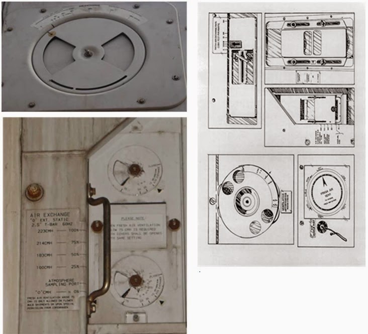
Figure 3: diagrams of the various vent-setting controls.
Care must be taken to ensure that the units for settings Fresh Air Exchange are not misread. Containers may be calibrated for Cubic Metres per Hour (CMH), Cubic Feet per Minute (CFM) or as a percentage (%) refer to Figure 3. All units are rated at 60hz for onboard vessels but while on shore the units run at 50hz, which may reduce the set amount of fresh air exchange by up to 23%.3.5. Controlled Atmosphere (CA) and Modified Atmosphere (MA or AFAM+)
Controlled or modified atmospheres normally are not provided in general refrigerated containers. In suitable containers, it is possible to provide CA or MA conditions (at additional cost) on a one-trip basis. For almost all CA/MA systems now in use the containers must meet a stringent gas-tightness specification and are usually fitted with a plastic sheet inside the doors to avoid the possible problems of leaking door seals. There are some containers especially designed for CA transport. CA containers allow the controlling of the container environment more precisely. Harvested fruit and vegetables continue to breathe until they are consumed or destroyed by decay or desiccation. Under normal circumstances these factors determine the lifespan of the product. The ripening process may be decelerated and the lifespan of a commodity may be prolonged by keeping the produce at optimal temperature coupled with the most effective blend of oxygen, carbon dioxide and nitrogen. Unlike CA and MA units, Automated Fresh Air Management (AFAM)+ uses fresh air exchanges controlled by sensors, which regularly read the O2 and CO2 levels inside the container. If the atmosphere is not at the pre-set AFAM+ level, the vent is adjusted mechanically to achieve the required levels.
3.6. Relative humidity
The quality of horticultural produce is directly affected by the relative humidity of the surrounding air. If the humidity is too low, the produce may wilt and shrivel, whilst if it is too high the produce may develop mould. There have been technical advances made in recent years to build refrigerated containers with advanced humidity control systems. Most require a relative humidity of around 90% to be maintained and this is maintained by the transpiration of the produce, when the ventilation and temperature controls of the container are set at an optimal level. Modern containers with advanced humidity control systems are equipped with a water source, a pump and a water atomiser that
introduces moisture into the container’s air stream. Some reefer containers are fitted with de-humidification equipment, which can reduce the relative humidity of the container to a level of between 50 and 80%.
3.7. Container damage
Every precaution must be taken to ensure that the container and its machinery is not damaged during transport or packing. While the use of freight containers substantially reduces the physical hazards to which cargo is exposed to, improper or careless packing of cargoes may result in serious and costly damage to the container.
The front end of the container houses the machinery, its evaporator and the air circulation system. This machinery is protected by grilles and reasonably robust panels, which can withstand normal wear and tear associated with acceptable methods of loading. However, the impact from careless stowing
(improper handling - such as throwing of cargo) could damage and distort the panels and machinery. Damage to the insulating envelope will result in loss of thermal efficiency leading to a reduction in insulating properties.
NOTE: Great care must be taken if forklifts are utilised to stow a refrigerated container. Adequate protection must be provided, in way of plywood or steel sheet flooring of appropriate strength, prior to utilising forklifts or other heavy equipment within the reefer container, to ensure that the ribs on the floor are not damaged.