Tuesday, February 14, 2017

Calculating The Length Of Lap For flat Joints

Formula
X = (Y – T – W) / L

Where
X = Length of lap area
Y = Safety factor desired
T = Tensile strength of weakest member
W = Thickness of weakest member
L = Shear strength of brazing filler metal

Example
What length of lap is needed to join 1.5 mm annealed Monel
sheet to a metal of equal or greater strength?

Solution
Y = 2 (desired safety factor for the assembly)
T = 482.6 MPa (tensile strength of annealed Monel sheet)
W = 1.5 mm
L = 172.4 MPa (arbitrary value for the average brazing
filler metal)

Result
X = (2 – 482.6 – 1.5) / 172.4 = 8.4 mm (length of lap)


Joint Properties

 
  • Shear strength The ability to resist the angular deformation, calculated as the sideways displacement of two adjacent planes divided by the distance between them. 
  • Butt tensile strength The ability to resist a force applied perpendicular to a given plane without rupturing. 
  • Stress rupture A fracture caused as a result of repeated physical strain. 
  • Hardness The ability of a material to resist scratching, abrasion, indentation or machinin g, as measured by a specifically chosen method or standard. 
  • Corrosion resistance The ability of a material to resist attack resulting from environmental, chemical or galvanic action. 
  • Oxidation resistance The ability of a material, particularly a metal, to resist reaction with oxygen, which can cause a loss of structural integrity resulting from the formation of undesirable oxide compounds. 
  • Microstructure The composition and microscopic structure of a material, as studied using metallographic methods. 
  • Joint configuration The design and shape of the joint chosen to join members that will meet or exceed structural requirements in service. Types of joint configurations include lap, butt, tee, tubing, tube thru plate and scarf (see section on Joint configuration).

Friday, February 10, 2017

Braze filler metal application by base material

Click To Enlarge

Available forms of braze filler metals

Braze products can be purchased in a variety of forms. Where available, customers can choose the form that is most convenient and efficient for their particular production needs.

Braze powder is produced by a process that generates clean, dense, spherical and dry particles. Each particle contains precise amounts of all the elements of a particular alloy and the powders are uniform and homogeneous.
Braze powder


Braze filler metal alloying elements

Various elements are added to braze filler metals. The purpose and behavior of these alloying elements are listed below.

Nickel (Ni) Provides desirable high temperature chemical and physical properties. Very compatible with other alloying elements.
Cobalt (Co) Has physical behavior that is very similar to nickel and can be freely substituted for a major portion of the nickel in any specific formulation. When added to nickel, it provides increased solubility, higher service temperature and increased matrix strength.

Manganese (Mn) Functions as a melting temperature suppressant.

Boron (B) Acts as a temperature suppressant, aids wetting through self-fluxing of oxides and contributes to high temperature strength and oxidation resistance. As an effective deoxidizer, boron provides additional joint strength and corrosion resistance. Can be readily diffused from the braze deposit.


Braze filler metal base material

Click To Enlarge

Vacuum furnace

A furnace with electrically heated elements that surround the workload and heat the brazing filler metal to the liquidus state so flow and capillary attraction are achieved. To permit brazing of alloys that are sensitive to oxidation at high temperatures, a pumping system is employed that removes oxygen. Gold, copper, nickel, cobalt, titanium and ceramic based filler metals are successfully vacuum brazed.


Retort or batch furnace

The furnace used can be refractory lined and heated by gas, oil or electricity. Atmospheres can be either a generated gas (endothermic or exothermic) or an inert gas such as argon or nitrogen. Hydrogen gas is also used for brazing filler metals that oxidize in other atmospheres. Copper, silver, nickel and gold based brazing filler metals can be brazed successfully in these types of furnaces.

Continuous furnace

Conveyor belts transport the pre-alloyed components through preheating, heating and post-heating zones where the braze alloy reaches temperature, then resolidifies during cooling. Silver and copper based brazing filler metals are most commonly used in these processes.

Induction brazing

Electric coils, which are designed for specific joint geometries, are used to heat the part and the brazing filler metal until the liquid metal flows via capillary attraction into the joint. This process is primarily used for brazing with copper and silver alloys. A typical application is a tube to tube assembly.

Torch brazing

A heating source supplied by a fuel gas flame. Gases include acetylene, hydrogen or propane. A typical application is to braze a tube into a fitting using copper or silver brazing filler metals.

Considerations for brazing success


Why braze?

  • Components can be batch processed
  • Brazing is production and cost efficient
  • Component distortion is minimized or eliminated
  • Base metal dilution is low
  • Process thermal cycles are predictable
  • Joining of dissimilar materials can be achieved
  • Thin-to-Thin or Thin-to-Thick members can be joined
  • Small and wide gap sizes can be filled
  • Specialized labor is not required

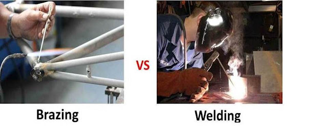
How is brazing different from welding?

Welding is a joining process wherein metallic components are joined through fusion (melting) or recrystallization of the base metal by applying heat, pressure or both. This process differs from brazing, where only the filler metal melts during processing.

How is soldering different from brazing?

Soldering is a joining process wherein metals are bonded together using a non-ferrous filler metal with a melting (liquidus) temperature lower than 450 °C (840 °F). Whenever the filler metal liquidus is greater than 450 °C (840 °F), the joining process is considered to be a brazing process rather than a soldering process.

What is brazing?

Brazing is a joining process wherein metals are bonded together using a filler metal with a melting (liquidus) temperature greater than 450 °C (840 °F), but lower than the melting temperature of the base metal. Filler metals are generally alloys of silver (Ag), aluminum (Al), gold (Au), copper (Cu), cobalt (Co) or nickel (Ni).

An Introduction to Brazing

An Introduction to Brazing

Fundamentals .
What is brazing?
How is soldering different from brazing?
How is brazing different from welding?
Why braze?
Considerations for brazing success.
Heat Sources for Brazing.
Torch brazing.
Induction brazing.
Continuous furnace.
Retort or batch furnace.
Vacuum furnace.
Braze Filler Metals.
Braze filler metal base material .
Braze filler metal alloying elements .
Available forms of braze filler metals.
Braze filler metal application by base material.
Braze Joint Design. 
Joint properties. 
Calculating the length of lap for flat joints. 
Joint configuration.
Brazing . (Coming soon)
Capillary braze action. (Coming soon)
Wetting in braze joints. (Coming soon)
Typical heating and cooling cycle for furnace brazing. (Coming soon)
Vapor pressure curves for vacuum brazing. (Coming soon)
Braze joint morphology. (Coming soon)
Supplementary Processing Elements . (Coming soon)
Braze procedure. (Coming soon)
Safety. (Coming soon)
Brazing Tips . (Coming soon)
Glossary of Brazing Terms. (Coming soon)

Thursday, February 9, 2017

REFRIGERATION TOOLS AND EQUIPMENT - The vacuum gauge


REFRIGERATION TOOLS AND EQUIPMENT - Refrigerant transfer hoses and accessories


REFRIGERATION TOOLS AND EQUIPMENT - Service port quick coupler

Service port quick coupler

REFRIGERATION TOOLS AND EQUIPMENT -Core removal tools

Core removal tools
Easy and quick core removal without refrigerant emission

REFRIGERATION TOOLS AND EQUIPMENT - Piercing plier (adjustable)

Enables immediate piercing/access on any refrigerant tubing from 5 to 22 mm

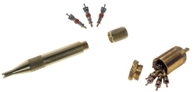
REFRIGERATION TOOLS AND EQUIPMENT - Core valve removal tool

Core valve removal tool
For removing and replacing valve cores in ‘Schrader’-valves and charging hoses
Tools contain spare valve cores

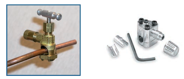
REFRIGERATION TOOLS AND EQUIPMENT - Piercing valve

Piercing valve
Enables piercing/access to any refrigerant tubing from 5 to 16 mm

REFRIGERATION TOOLS AND EQUIPMENT - Charging hose and cylinder connectors

Charging hose and cylinder connectors

  1. Can valve/extracting of refrigerants out of small disposable refrigerant cylinders
  2. 21.8 mm adapter and gasket for connecting a charging hose with 1/4” SAE thread
  3. Stand for liquid charge, disposable cylinder connection to ensure a firm standing of the cylinder on the charging scale


Search "Charging hose and cylinder connectors" on google image for more picture

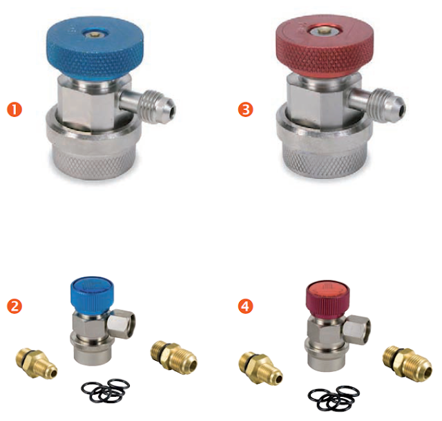
REFRIGERATION TOOLS AND EQUIPMENT - Automotive (MAC) manual quick service couplers for HFC-134a

Automotive (MAC) manual quick service couplers for HFC-134a

REFRIGERATION TOOLS AND EQUIPMENT - Refrigerant recovery cylinder

Refrigerant recovery cylinder

REFRIGERATION TOOLS AND EQUIPMENT - Heating belt with thermostat

hvac
Heating belt with thermostat

REFRIGERATION TOOLS AND EQUIPMENT - Refrigerant and oil contamination test kit

Refrigerant and oil contamination test kit


REFRIGERATION TOOLS AND EQUIPMENT - Oil test kit for mineral and alkylbenzene lubricant

Oil test kit for mineral and alkylbenzene lubricant

REFRIGERATION TOOLS AND EQUIPMENT - Oil test kit for polyol ester (POE) lubricants

REFRIGERATION
Oil test kit for polyol ester (POE) lubricants

REFRIGERATION TOOLS AND EQUIPMENT - Retrofit test kit

HVAC
Retrofit test kit

REFRIGERATION TOOLS AND EQUIPMENT - Refractometer

Refractometer
Refractometer

REFRIGERATION TOOLS AND EQUIPMENT - Oil pump

oil pump
Oil pump

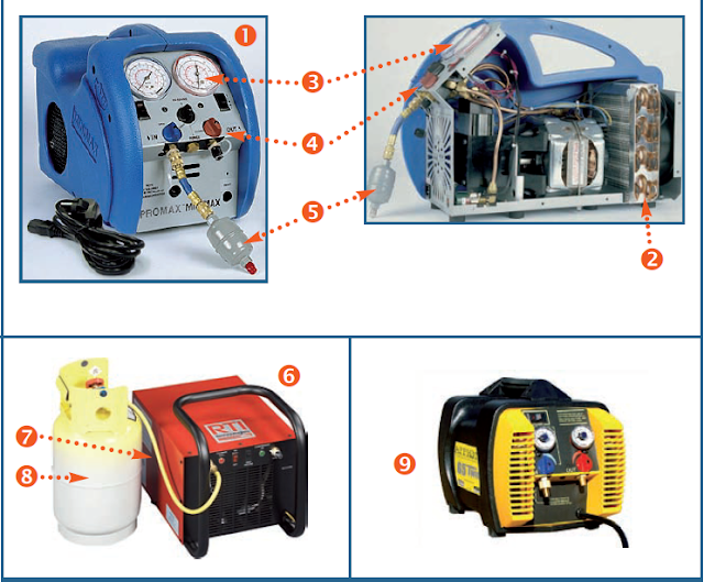
Equipment for Recovery, Recycling, Reclamation and Evacuation (RRRE) - Refrigerant recovery unit

Refrigerant recovery unit

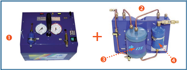
Equipment for Recovery, Recycling, Reclamation and Evacuation (RRRE) - Recovery, recycling, evacuation and charging unit

Recovery, recycling, evacuation and charging unit 1

Equipment for Recovery, Recycling, Reclamation and Evacuation (RRRE) - Refrigerant recovery and recycling unit

Refrigerant recovery and recycling unit
Refrigerant recovery and recycling unit 1

Sunday, February 5, 2017

Marine Refrigerated Container (Reefer) Training Module Year 2017

If you want original training module in web page html format please click here
Click Here For Download PDF Format
Update on 14.02.2017 Repair Broken link

Thanks For Visit!!!

Microprocessor Performance and Trends

Microprocessor Performance and Trends

The number of transistors available has a huge effect on the performance of a processor. As seen earlier, a typical instruction in a processor like an 8088 took 15 clock cycles to execute. Because of the design of the multiplier, it took approximately 80 cycles just to do one 16-bit multiplication on the 8088. With more transistors, much more powerful multipliers capable of single-cycle speeds become possible.

More transistors also allow for a technology called pipelining. In a pipelined architecture, instruction execution overlaps. So even though it might take five clock cycles to execute each instruction, there can be five instructions in various stages of execution simultaneously. That way it looks like one instruction completes every clock cycle.

Many modern processors have multiple instruction decoders, each with its own pipeline. This allows for multiple instruction streams, which means that more than one instruction can complete during each clock cycle. This technique can be quite complex to implement, so it takes lots of transistors. 

Microprocessor Instructions

Microprocessor Instructions

Even the incredibly simple microprocessor shown in the previous example will have a fairly large set of instructions that it can perform. The collection of instructions is implemented as bit patterns, each one of which has a different meaning when loaded into the instruction register. Humans are not particularly good at remembering bit patterns, so a set of short words are defined to represent the different bit patterns. This collection of words is called the assembly language of the processor. An assembler can translate the words into their bit patterns very easily, and then the output of the assembler is placed in memory for the microprocessor to execute.

Here's the set of assembly language instructions that the designer might create for the simple microprocessor in our example:


Microprocessor Memory

Microprocessor Memory

The previous section talked about the address and data buses, as well as the RD and WR lines. These buses and lines connect either to RAM or ROM -- generally both. In our sample microprocessor, we have an address bus 8 bits wide and a data bus 8 bits wide. That means that the microprocessor can address (28) 256 bytes of memory, and it can read or write 8 bits of the memory at a time. Let's assume that this simple microprocessor has 128 bytes of ROM starting at address 0 and 128 bytes of RAM starting at address 128.

ROM stands for read-only memory. A ROM chip is programmed with a permanent collection of pre-set bytes. The address bus tells the ROM chip which byte to get and place on the data bus. When the RD line changes state, the ROM chip presents the selected byte onto the data bus.

Microprocessor Logic

Microprocessor Logic

To understand how a microprocessor works, it is helpful to look inside and learn about the logic used to create one. In the process you can also learn about assembly language -- the native language of a microprocessor -- and many of the things that engineers can do to boost the speed of a processor.


A microprocessor executes a collection of machine instructions that tell the processor what to do. Based on the instructions, a microprocessor does three basic things:

How Microprocessors Work

How Microprocessors Work

The computer you are using to read this page uses a microprocessor to do its work. The microprocessor is the heart of any normal computer, whether it is a desktop machine, a server or a laptop. The microprocessor you are using might be a Pentium, a K6, a PowerPC, a Sparc or any of the many other brands and types of microprocessors, but they all do approximately the same thing in approximately the same way. A microprocessor -- also known as a CPU or central processing unit -- is a complete computation engine that is fabricated on a single chip. The first microprocessor was the Intel 4004, introduced in 1971. The 4004 was not very powerful -- all it could do was add and subtract, and it could only do that 4 bits at a time. But it was amazing that everything was on one chip. Prior to the 4004, engineers built computers either from collections of chips or from discrete components (transistors wired one at a time). The 4004 powered one of the first portable electronic calculators.

What is a Microprocessor?


The microprocessor, also known as the Central Processing Unit (CPU), is the brain of all computers and many household and electronic devices. Multiple microprocessors, working together, are the "hearts" of datacenters, super-computers, communications products, and other digital devices.

          The first microprocessor was the Intel 4004, introduced in 1971. The 4004 was not very powerful; it was primarily used to perform simple mathematical operations in a calculator called “Busicom.”

Difference Between PLC & Microprocessor

A Programmable Logic Controller (PLC) is type of computer designed specifically for industrial applications. A microprocessor is the Central Processing Unit (CPU) of a computer.

Differences

All PLCs contain one or more microprocessors, but not all microprocessors are used in PLCs. Desktop computers, appliances, automobiles and consumer electronics are all likely to contain one or more microprocessors.

Features

A microprocessor is only one component of an electronic device and requires additional circuits, memory and firmware or software before it can function. A PLC is a complete computer with a microprocessor. A PLC can be programmed or reprogrammed to control different types of devices, using relatively simple programming languages such as Ladder Logic, which resembles a circuit diagram with switches, coils, relays and other electrical components, representing operators such as True/False, counters, timers and numeric computations.

What is a Programmable Logic Device?


A PLD, or programmable logic device, is an electronic component that is used in order to build digital circuits that are reprogrammable. A programmable logic device does not have a defined function once manufactured, unlike a logic gate and has to be programmed before it can be used.

Types of Programmable Logic Devices

There are several different kinds of programmable logic devices at Future Electronics. We stock many of the most common types categorized by several parameters including Programmable Type, Number of I/O Lines, Supply Voltage, Memory Density, System Gates, Packaging Type and many other parameters specific to the type of programmable logic device. Our parametric filters will allow you to refine your search results according to the required specifications.

PLC Basics

Definition of a PLC

What is a PLC? 

A Programmable Logic Controller, or PLC for short, is simply a special computer device used for industrial control systems. They are used in many industries such as oil refineries, manufacturing lines, conveyor systems and so on. Where ever there is a need to control devices the PLC provides a flexible way to "softwire" the components together.


The basic units have a CPU (a computer processor) that is dedicated to run one program that monitors a series of different inputs and logically manipulates the outputs for the desired control.  They are meant to be very flexible in how they can be programmed while also providing the advantages of high reliability (no program crashes or mechanical failures), compact and economical over traditional control systems.

Direct System/ Analog in HVAC

Direct system

Definition

heatingair conditioning, or refrigerating system that employs no intermediate heat exchanger to heat or cool a space.
Explore Below Image: 


Saturday, February 4, 2017

Fresh air Make up Vent

Fresh air Make up Vent


  1. Purpose of this vent is to provide ventilation for commodities that requires fresh air circulation and must be closed when transporting frozen foods.
  2. Air exchange depends upon static pressure differential which will vary depending upon how container is loaded.

Controlled Atmosphere

CONTROLLED ATMOSPHERE STORAGE

Controlled atmosphere storage is a system for holding produce in an atmosphere that differs
substantially from normal air in respect to CO2 and O2 levels. Controlled atmosphere storage refers to the constant monitoring and adjustment of the CO2 and O2 levels within gas tight stores or containers. The gas mixture will constantly change due to metabolic activity of the respiring fruits and vegetables in the store and leakage of gases through doors and walls. The gases are therefore measured periodically and adjusted to the predetermined level by the introduction of fresh air or nitrogen or passing the store atmosphere through a chemical to remove CO2.

There are different types of controlled atmosphere storage depending mainly on the method or degree of control of the gases. Some researchers prefer to use the terms ”static controlled atmosphere storage” and “flushed controlled atmosphere storage” to define the two most commonly used systems. “Static” is where the product generates the atmosphere and “flushed” is where the atmosphere is supplied from a flowing gas stream, which purges the store continuously. Systems may be designed which utilize flushing initially to reduce the O2 content then either injecting CO2 or allowing it to build up through respiration, and then maintenance of this atmosphere by ventilation and scrubbing.


Humidity Management

The humidity level has a direct infl uence on the quality of your produce – especially as
it pertains to shelf life.

Low humidity levels cause:
  • Dehydration of produce
  • Weight loss
  • Negative changes in produce appearance

High humidity levels cause:
  • Growth of mold and bacteria
  • Fungal disorders

Relative humidity in the air that circulates in a reefer container depends on the
following key factors:
  • Rate of fresh air ventilation
  • Relative humidity of fresh air entering into the container
  • Temperature of the evaporator coil relative to the dew point of the air in the container
  • Vapor pressure defi cit, which will infl uence the rate of moisture transfer between the air and commodity
  • Carriage and produce temperature
  • Packaging
  • Type of commodity (respiration rate)

Atmosphere Management (ventilation)

Normal atmosphere consists of 78% nitrogen (N2), 21% oxygen (O2) and 0.03% carbon dioxide (CO2). An unventilated container of fruit, with rapid respiration rates, can quickly change the atmosphere, reversing the normal levels of oxygen and carbon dioxide in less than 24 hours. That could be disastrous, because too little oxygen or too much carbon dioxide can lead to spoilage.

Atmospheric composition is important to fruit and vegetables because they ‘breathe’ or respire, consuming oxygen and producing carbon dioxide. Optimal atmospheric control can slow down the rate of produce respiration and delay ripening beyond what refrigeration alone can do.

Atmosphere management involves:

  • Reducing oxygen
  • Increasing or removing carbon dioxide
  • Removing ethylene and other volatiles

How do integral refrigerated containers work?

In contrast to porthole containers, integral refrigerated containers are equipped with their own refrigeration unit. This normally relies on a three-phase electrical power supply. For information on the electrical data of this container type, see Section 8.1.

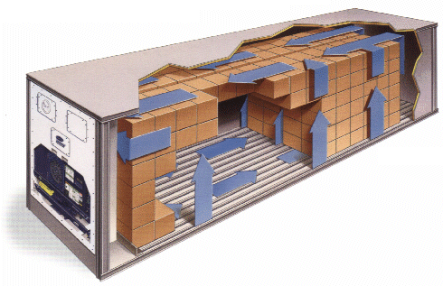
Cold air flows through and around the goods in the container. This air is blown in through the gratings in the floor and then drawn off again below the container ceiling. The circulating fans then force the air through the air cooler, which also acts as the evaporator in the cold circuit, and back through the gratings into the cargo (see Figure 11).


Figure 11: Air flow in an integral refrigerated container


Sensor Or Thermistor


How A Sensor/Thermistor Works

thermistor is a component that has a resistance that changes with temperature. There are two types of thermistor, those with a resistance that increase with temperature (Positive Temperature Coefficient – PTC) and those with a resistance that falls with temperature (Negative Temperature Coefficient – NTC).

how_a_thermistor_works_1

Temperature coefficient:

The most common type of thermistors are those in which resistance decreases as the temperature increases (NTC).

Relay


Fuse

What is a Fuse:

The fuse is an electronic device, which is used to protect circuits from over current, overload and make sure the protection of the circuit. There are many types of fuses available in the market, but function of all these fuses is same.
Fuse consists of a low resistance metallic wire enclosed in a non combustible material. Whenever a short circuit, over current or mismatched load connection occurs, then the thin wire inside the fuse melts because of the heat generated by the heavy current flowing through it. Therefore, it disconnects the power supply from the connected system. In normal operation of the circuit, fuse wire is just a very low resistance component and does not affect the normal operation of the system connected to the power supply.

Types of Fuses:

There are different types of fuses available in the market and they can be categories on the basis of Different aspects.Good to know: Fuses are used in AC as well as DC circuits.


What is the difference between a contactor and a relay?

Relays are usually cheaper and lower in their performance capabilities for signal switching and load handling than contactors. While contactors and relays are both used in engineering applications to switch signals and power connections, relays are used in applications where speed and power are not as critical.


Solid-state relays are the most commonly used circuit component to control load currents. These relays are constructed from solid-state switches such as triacs, silicon-controlled rectifiers and power transistors. The type of switches used in relay design depends on the amount of load current, potential difference and switching speed that the relay is expected to handle.

Phase contactor

contactor is an electrically controlled switch used for switching an electrical power circuit, similar to a relay except with higher current ratings. A contactor is controlled by a circuit which has a much lower power level than the switched circuit.Contactors come in many forms with varying capacities and features.


Transformers

Electricity transformers

by Chris Woodford. Last updated: December 28, 2016.
The mighty power lines that criss-cross our countryside or wiggle unseen beneath city streets carry electricity at enormously high voltages from power plants to our homes. It's not unusual for a power line to be rated at 400,000 to 750,000 volts! But the appliances in our homes use voltages thousands of times smaller—typically just 110 to 250 volts. If you tried to power a toaster or a TV set from an electricity pylon, it would instantly explode! (Don't even think about trying, because the electricity in overhead lines will almost certainly kill you.) So there has to some way of reducing the high voltage electricity from power plants to the lower voltage electricity used by factories, offices, and homes. The piece of equipment that does this, humming with electromagnetic energy as it goes, is called a transformer. Let's take a closer look at how it works!
Photo: Substation: A typical electricity transformer supplying homes in the small English village where I live. It's about 1.5m (5ft) high and the output is probably several thousand volts.